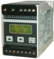
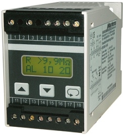
insulation guard | IW 1000
1.136,00 EUR
inkl. 19 % USt -> Preis zzgl. Versandkosten
Lieferzeit bzw. Fertigungszeit variiert - bitte erfragen!
Art.Nr.: IW1000Produktbeschreibung
general information:
The isolation-guard IW1000 is used for insulation-monitoring in machines and systems with ungrounded voltage systems. The universal design allows the monitoring of all AC and DC systems.
Common insulation guards, working with pulse measuring mode, are running with fixed
pulse widths. For well operation, they must be adapted manually to the actual leakage capacity of the system. There are also insulation guards available, working with self adapting pulse width. However these devices need a long measuring time because the result will be at least available, when loading voltage will find its maximum (no more change in load voltage). With the time optimized measuring method of the IW1000, insulation resistance and leakage capacity will be calculated after 2-time constants. Therefor the reaction time of the IW1000 is very short.
pulse widths. For well operation, they must be adapted manually to the actual leakage capacity of the system. There are also insulation guards available, working with self adapting pulse width. However these devices need a long measuring time because the result will be at least available, when loading voltage will find its maximum (no more change in load voltage). With the time optimized measuring method of the IW1000, insulation resistance and leakage capacity will be calculated after 2-time constants. Therefor the reaction time of the IW1000 is very short.
- time optimized pulse measuring method
- 2 alarm output relays, 1 analog output
- automatic and manual self test
- acoustic alarm in case of malfunction
- devices for railway vehicles and healthcare facilities available
specifications:
| auxiliary energy |
|
| auxiliary voltage: | 230 V AC, 115 V AC, 24 V AC ±10 %; 16.8 to 33.6 V DC, 10.8 to 15.6 V DC |
| power consumption: | max. 4 VA |
| operating temp.: | -10°C to +55°C |
| option 01: | -25°C to +70°C |
| relative humidity: | ≤75 % annual mean acc. to DIN EN 50155, 95 % for 30 days all year continuously, seldom or low humidity does not lead to malfunctions or cancellations |
| CE conformity: | EN 60664-1, EN 61326-2-4, EN 50121-3-2, EN 60068-2-1/2/6/27 |
| add. for option 01: | EN 50155 in following points: EN 61373, EN 60068-2-27 |
| fire safety: | Fulfilment of fire safety requirements for railway vehicles acc. to the basic standard NFF16-101 paticulary (IEC) EN 60695-2-12 (Glow-wire testing temperature 850°C) and NFF16-102 particulary 6.2; 6.4; 6.5% |
| input | |
| Unom: | 0 to 690 V AC/DC; from UN >400 V operation only with cover clamp permitted |
| frequency range: | 16 2/3 Hz to 400 Hz |
| measuring circuit | |
| Umeas max.: | standard: ± 40 V health care: ± 20 V |
| Imeas max.: | standard: ± 220 μA health care: ± 110 μA |
| Ri DC: | 180 kΩ (2 x 360 kΩ parallel) |
| impedance Zi: | 180 kΩ (2 x 360 kΩ parallel) at 50 Hz |
| operating values | |
| AL1/AL2: | 1 kΩ to 5 MΩ x 1.1 (1.1 kΩ to 5.5 MΩ) programmable |
| accuracy: | ± 5 %, ± 1 kΩ in the range 1 kΩ to 5 MΩ |
| hysteresis: | 10 % to 100 % of the setpoint programmable |
| measuring time: | see table1 (data sheet) |
| system leakage capacity: | max. 500 μF |
| display | |
| type: | LCD Dot-Matrix, 2 lines 8 characters each, character height 5 mm, with back light |
| indicating range: | 1 kΩ to 9.9 MΩ |
| resolution: | 1 MΩ to 9.9 MΩ: 0.1 MΩ 1 kΩ to 999 kΩ: 1 kΩ |
| output | |
| relay SPDT: | < 250 V AC < 250 VA < 5 A; < 300 V DC < 50 W < 2 A |
| analog output: | 0 mA to 1 mA, RF (insulation resistance) |
| housing | |
| type: | makrolon 8020 UL94V-1 |
| weight: | approx. 390 g |
| connection: | screw terminals 4 mm2 |
| ingress protection: | housing IP40, terminals IP20, BGV A3 |
For further details p.r.t. data sheet:
instruction manual as .pdf:
 |